.png "Modbus example")
Modbus
Modbus is a serial communication protocol developed for use with its programmable logic controllers (PLCs).
Modbus
Modbus is a serial communication protocol developed for use with its programmable logic controllers (PLCs). bOS Modbus device is usually used for industrial solutions such as energy consumption metering and more advanced HVAC systems.
Tutorial videos
Working with Modbus
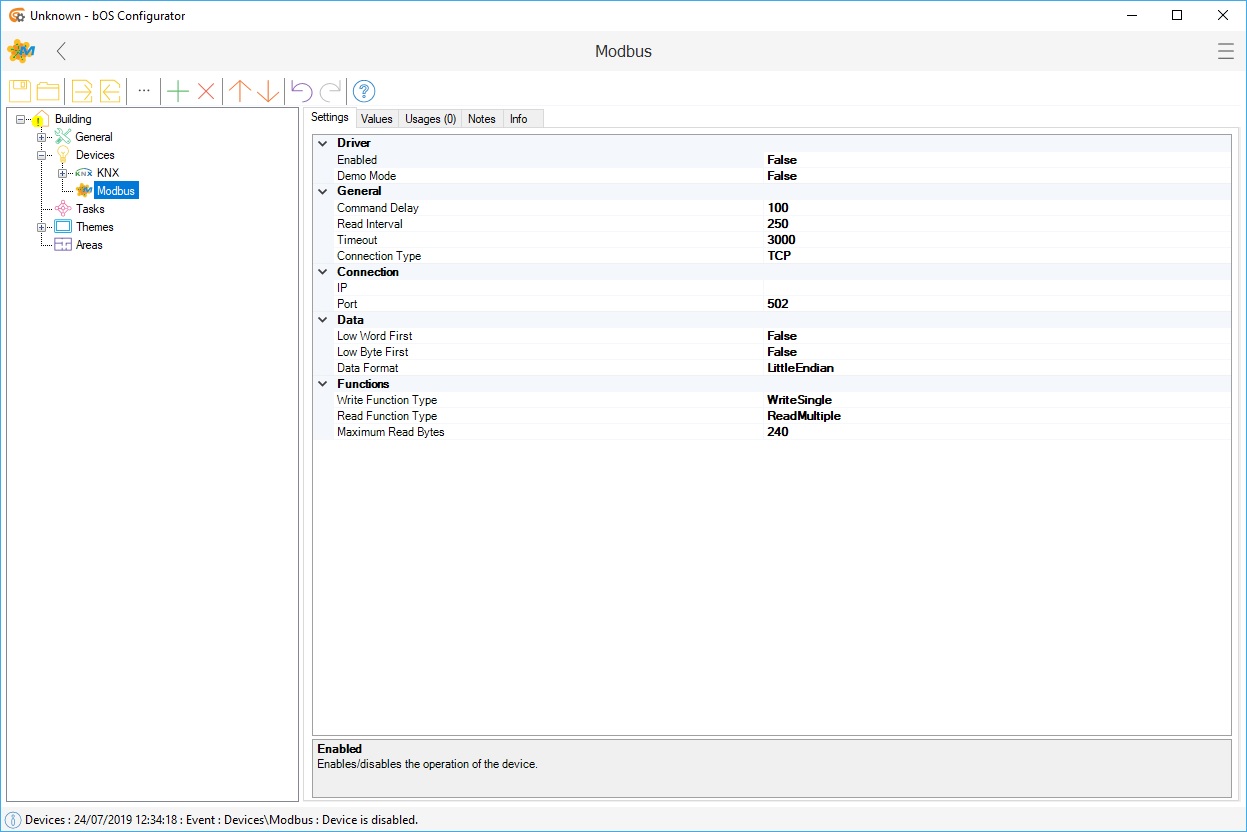
Picture 1: Modbus node
Modbus driver acts as a Modbus master device. Driver offers two types of connections (TCP or RTU) defined by the Connection Type setting. TCP connection has IP and Port settings. RTU connection has serial port settings (Serial Port, Baud Rate, Data Bits, Parity, Stop Bits and Handshake). RS-232 or RS-485 serial communication can be used with a suitable USB converter. Additional timeout delay can be set.
Modbus slave devices store data in four Modbus tables:
Discrete Output Coils: Read, Write
Discrete Input Contacts: Read only
Analog Input Registers: Read only
Analog Output Holding Registers: Read, Write
Very important thing to note is that, bOS starts counting Modbus addresses or devices with address number 0 and not with 1 like many other modbus softwares. If the manual of the device starts modbus addresses with 1 and the modbus address is e.g. 2001, bOS address would be 2000.
Each table has 9999 values. Each coil or contact is 1 bit and assigned a data address between 0000 and 9998. Each register is 1 word = 16 bits = 2 bytes and also has data address between 0000 and 9998.
Modbus data is converted by the following data point nodes: DPT Boolean, DPT Double, DPT Integer, DPT UInt. The appropriate data Address should be entered for each data point. Slave addressing can be used for each data point. Use Slave Addressing and Slave Address settings are available. The data point nodes offers Value value to use on user interface and in tasks.
Folder node can be used to group different zones and partitions.
DPT Boolean
Node converts the data from Coils and Inputs table, defined by the Table setting.
DPT Double
Node converts the data from Input Registers and Holding Registers table, defined by the Table setting. The data can be converted from IEEE 32 Bit Float, Signed 16 Bit Integer, Unsigned 16 Bit Integer or Signed 32 Bit Integer. In case of IEEE 32 Bit Float and Signed 32 Bit Integer, 2 holding registers (4 bytes) will be read.
DPT Integer
Node converts the data from Input Registers and Holding Registers table, defined by the Table setting. The appropriate data Address should be entered. The data can be converted from Signed 16 Bit Integer, Unsigned 16 Bit Integer or Signed 32 Bit Integer. In case of Signed 32 Bit Integer, 2 holding registers (4 bytes) will be read.
DPT UInt
Node converts the data from Input Registers and Holding Registers table, defined by the Table setting. The appropriate data Address should be entered. The data can be converted from Unsigned 32 Bit Integer. 2 holding registers (4 bytes) will be read.