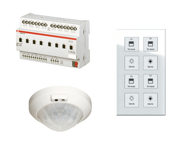
.png "KNX example")
KNX
KNX is the worldwide open standard for all applications in home and building control – lighting, shades, HVAC, energy consumption, irrigation and more.
KNX
KNX is the worldwide open standard for all applications in home and building control – lighting, shades, HVAC, energy consumption, irrigation, and more.
Tutorial videos
Working with KNX
Our KNX software (driver) supports communication with EIB/KNX installations over IP, USB, and serial adapters, our Jigsaw KNX server also has a KNX module built-in which connects directly to the KNX bus for communication and integration.
Before creating the bOS configuration, configure the KNX system with ETS or contact your installer to get a Group Address export file (.esf or .xml (ETS 5)).
Picture 1: KNX node
Driver supports the following connection types:
KNX IP
KNXnet / IP (Falcon)
KNXnet / IP Routing (Falcon)
USB (Falcon)
EIBLib / IP (Falcon)
Serial FT1.2
Custom Jigsaw KNX driver
It is necessary to ensure that the KNX IP interface is on the same network as the server machine. It is recommended that the static IP address is set on the interface. KNX IP interfaces sometimes require a second KNX interface to program the static IP. Remote programming is also available over KNX 3671 port.
Depending on the KNX project that is imported into bOS, multiple different KNX data points must be added in. bOS supports all KNX data points that are currently available. All data points are listed and described in the official KNX interwork document.
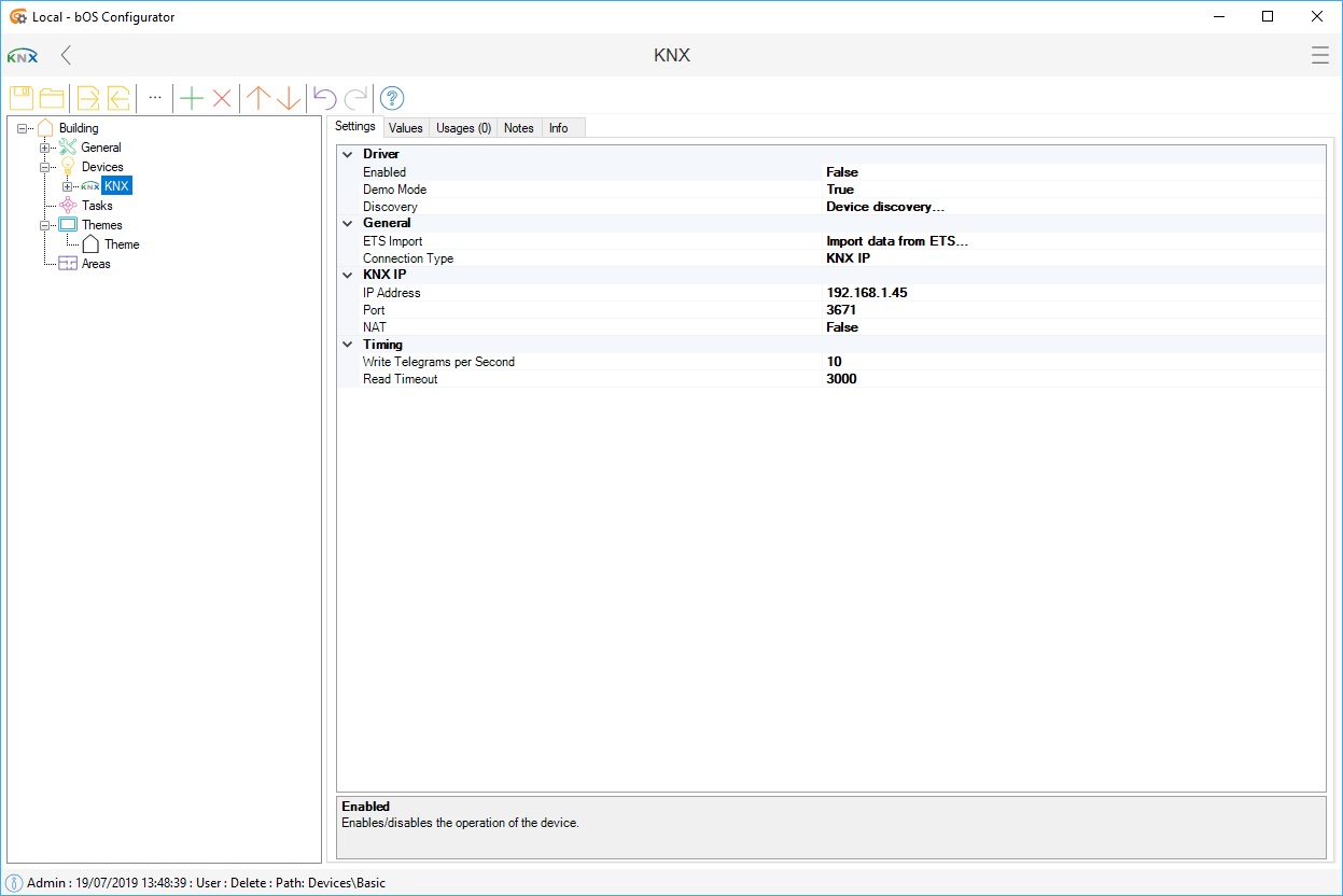
Picture 2: KNX data type node settings
Address setting is the group address. Currently, only three-level group addresses are supported (e.g. 0/0/0).
Status Address is used for receiving object values. If Status Address is set, values received on Address are ignored. Multiple status addresses can be entered, separated by commas.
Value Type sets the type of the group address (type, unit, image). This setting can be configured manually for each group address, or configured when importing from ETS using our import wizard.
Communication flags and cyclical sending can be used for each data point. Multiple actions can be set when the device is connected (read or write to address).
KNX IP
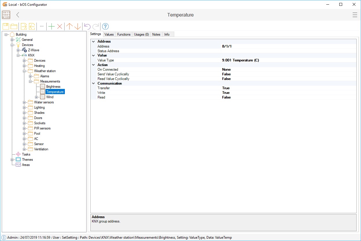
Under KNX IP you can find your IP address, port, and your NAT (Network Address Translation). If you don't know your KNX IP address, you can use Discover function, which will search for your KNX device on your local network, find its IP and use it in your configuration. If a bigger project consists of more KNX IP interfaces (any KNX IP interface or Jigsaw KNX server), bOS allows communication between multiple different KNX IP interfaces.
Picture 3: Discover function
Importing database from ETS
Datapoint definitions can be imported from a Konnex OPC Server Export file (.esf) or Group Address export file (.xml (ETS 5)) by clicking on the Import from ETS button.
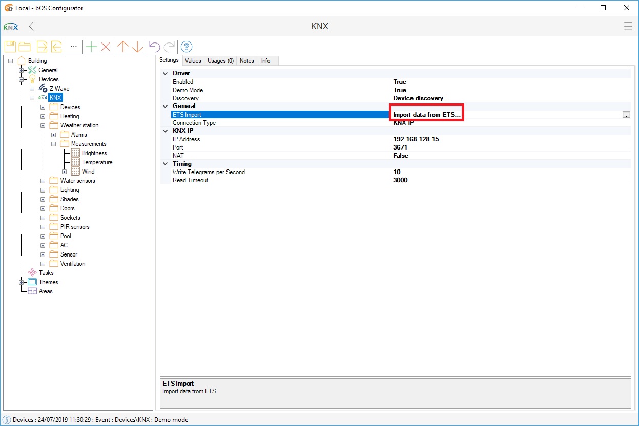
Picture 4: ETS import function
After selecting the correct ETS (.esf, XML) project, all group addresses from the project will be displayed. Most of the data points will be added automatically, but some need to be added manually.
NOTE: To edit multiple data types (same type), left-click and drag up/down to select, right-click on the selection and set the desired data type. Status addresses should also be set for every control group address, to save time in later configuration.
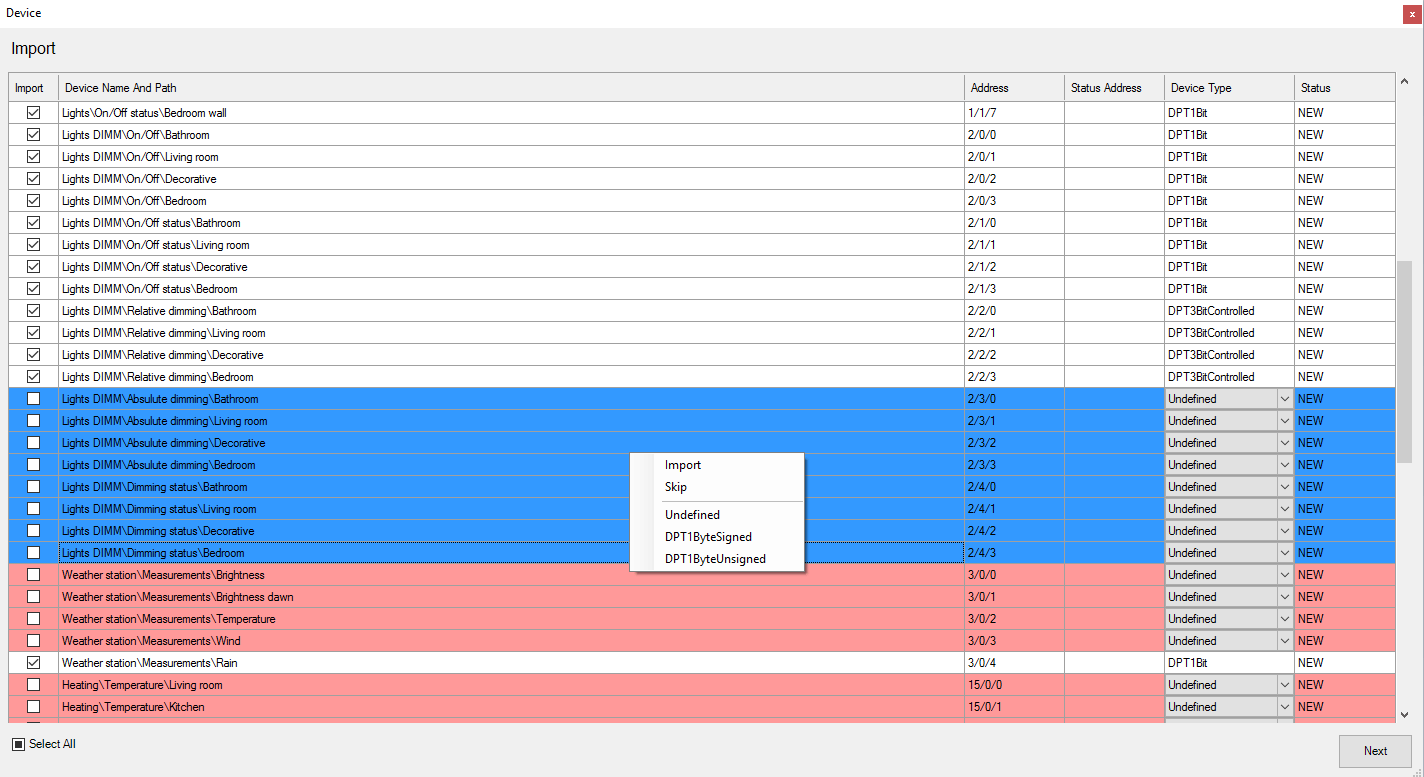
Picture 5: Import from multiple select
In next step, value templates should be selected in order to use them in scenes, schedules, themes... They are used to generate the control buttons for scene settings and automatic control creation. Group addresses are clearly visible by their name or address number.
Select the desired group address and add the correct device type, this will automatically set type, image, and correct unit. All values can be later changed after the ets import by manually selecting the group address and tweaking the settings.
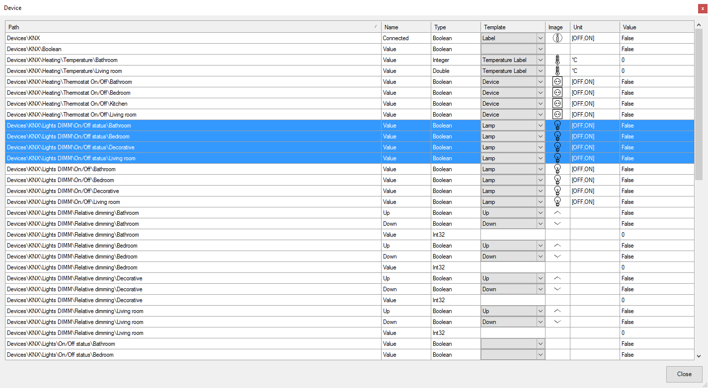
Picture 6: Device settings
KNX VISUALIZATION
Switching lights
Lights or relay outputs are usually controlled with the following data points:
Switch on/off: DPTBoolean
Switch status: DPTBoolean
You can use "Switch status" optionally. The Address from the "Switch status" should be copied to the Status address of the "Switch on/off" node. This way we have a single node (and single button) to control the output with status feedback. Multiple status addresses can be used if necessary. DPTBoolean data points and types can also be used to control other on/off devices, not just lights.
Dimming lights
Dimmable lights are usually controlled with the following data points:
Switch on/off: DPTBoolean
Relative dimming: 3BitControlled
Brightness value: DPT8BitUnsigned (0-100%)
Brightness status: DPT8BitUnsigned (0-100%)
The control in percentage is easier to operate and automate. Use the "Brightness value" object for dimming control if this is supported by the KNX module. You must import the "Brightness value" and "Brightness status" objects from the ETS. The Address from the "Brightness status" should be copied to the Status address of the "Brightness value" node. This way we have a single node (and single button) to control the dimmer with status feedback.
Some modules don't support "Brightness value" control. Alternatively, you can also control dimming with the "Switch on/off" and "Relative dimming" data points directly. This way you need to create 3 buttons to control the shades from theme panels:
On/off button: Toggle button linked to "Switch on/off.Value".
Dimm down button: MouseDownButton button linked to "Relative dimming.FalseToggle"
Dimm up button: MouseDownButton button linked to "Relative dimming.TrueToggle"
Or you can also use one of our pre-built examples that are available in the KNX node. To add the dimming example into the project, select KNX node, and select Add function. Select KNX Folder and select Dimmer Up/down under Templates. This will create a dimming folder with group address options, icons, and already made visualisation option to use in the project.
Controlling shades
Shades are usually controlled with the following data points:
Move up/down: DPTBoolean
Stop up/down: DPTBoolean
Move to position: DPT8BitUnsigned, Value Type = DPT_Scaling (0-100%)
Status position: DPT8BitUnsigned, Value Type = DPT_Scaling (0-100%)
The control in percentage is easier to operate and automate. Use the "Move to position" object for blinds control if this is supported by the KNX module. You must import the "Move to position" and "Status position" objects from the ETS. The Address from the "Status position" should be copied to the Status address of the "Move to position" node. This way we have a single node (and single button) to control the shades with status feedback.
Some modules don't support "Move to position" control. Alternatively, you can also control blinds with the "Move up/down" data points directly. This way you need to create 3 buttons to control the shades from theme panels.
Stop button: SetButton linked to "Stop up/down.Value", SetButtonValue = false
Down button: SetButton linked to "Move up/down.Value", SetButtonValue = true
Up button: SetButton linked to "Move up/down.Value", SetButtonValue = false
Or you can also use one of our pre-built examples that are available in the KNX node. To add the shading example into the project, select KNX node, and select Add function. Select KNX Folder and select Shade Up/down under templates. This will create a shading folder with group address options, icons, and already made visualization options to use in the project.
Controlling modes and scenes
Different modes (e.g. thermostat mode, heat pump operation mode...) or scenes are usually represented with a number:
Thermostat Mode: DPT8BitUnsigned, Value Type = DPT_Value_1_Ucount (0-255)
Call scene: DPT8BitUnsigned, Value Type = DPT_Value_1_Ucount (0-255)
NOTE: Value type should be set to DPT_Value_1_Ucount, which means there will be no conversion of data (0-255).

